CNC Machining Tolerances and Precision: What Engineers and OEMs Need to Know
When a part doesn’t fit, fails under load, or creates assembly problems on the line, the root cause often traces back to one thing: tolerance. Understanding CNC machining tolerances and precision isn’t just technical background knowledge for engineers — it’s a practical tool for designing better parts, managing costs, and building stronger supplier relationships. Get it right at the design stage and you eliminate a category of problems before they ever reach the shop floor.
At AP Precision Metals, we’ve spent over 20 years manufacturing high-precision metal components for OEMs across industries — from defense and electronics to energy and industrial equipment. Our ISO 9001:2015-certified quality management system is built around holding tight tolerances consistently at production volume. This guide draws on that experience to break down what tolerances mean, how they’re achieved, what drives their cost, and how to make smarter decisions when specifying precision metal parts.
Machining Tolerance Is the Foundation of Every Precision Metal Part
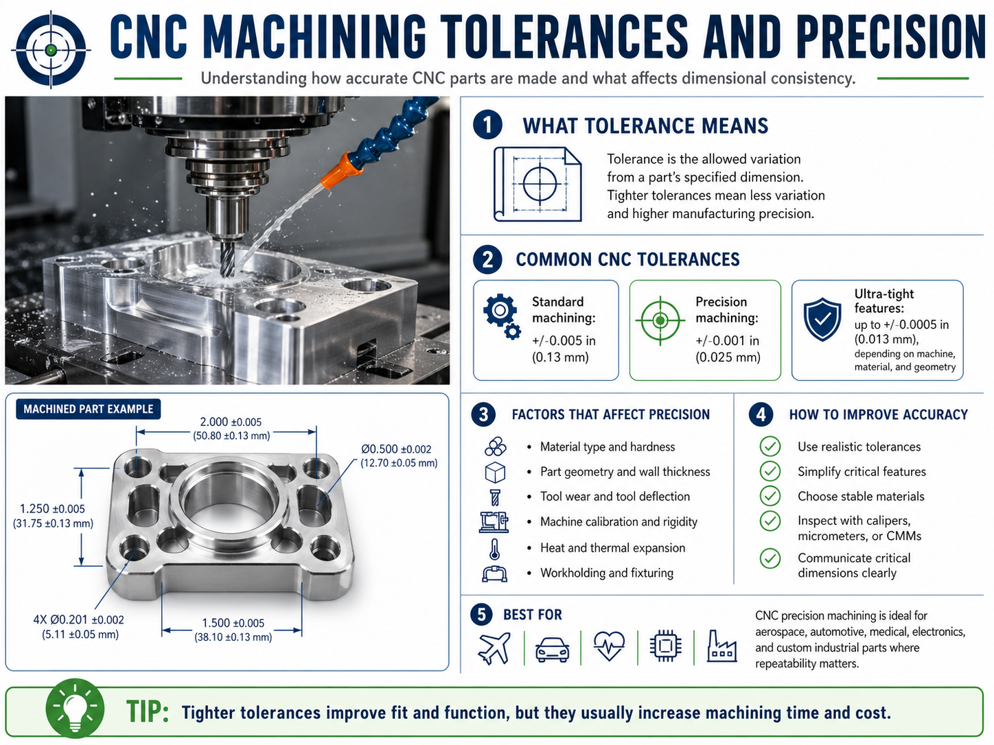
A machining tolerance defines the acceptable range of dimensional variation for a manufactured part. When an engineer specifies a shaft diameter of 25.00 mm with a tolerance of ±0.05 mm, they’re stating that any finished diameter between 24.95 mm and 25.05 mm is acceptable for that part’s function. Every dimension on a technical drawing — length, width, hole diameter, thread depth, surface profile — can carry its own tolerance specification.
Tolerance is distinct from accuracy. Accuracy describes how close a measured value is to the intended nominal dimension. Tolerance describes the permissible window of deviation. Both matter, but tolerance is the design decision that drives machining strategy, quality inspection, and ultimately, cost.
Two types of tolerances appear most often in CNC fabrication work:
- Dimensional tolerances: Control the size of a feature — length, diameter, depth, wall thickness. Usually expressed as bilateral (±) or unilateral (+0.00 / -0.05) values.
- Geometric tolerances (GD&T): Control the shape, orientation, and position of features relative to each other. Expressed using standardized symbols per ASME Y14.5 or ISO 1101, covering properties like flatness, perpendicularity, true position, and runout.
The Most Common CNC Tolerance Standards Explained
Several established standards govern how tolerances are communicated and interpreted between design teams and manufacturers. Knowing which standard applies to your parts — and what it actually permits — prevents costly misunderstandings.
ISO 2768 (General Tolerances)
ISO 2768 is the most widely used general tolerance standard in international manufacturing. It defines four classes of linear dimensional tolerance and two classes of geometric tolerance, applied when specific tolerances aren’t called out individually on a drawing.
- f (fine): For high-precision components requiring careful machining
- m (medium): The most common class for general machined parts
- c (coarse): For less critical dimensions or rougher processes
- v (very coarse): For castings, heavy weldments, or non-functional surfaces
ASME Y14.5 (GD&T)
ASME Y14.5 is the dominant standard in North American manufacturing for geometric dimensioning and tolerancing. It provides a precise, symbolic language for specifying the allowable variation in form, fit, and function of every feature on a part. For OEMs supplying into aerospace, defense, or medical sectors, GD&T per ASME Y14.5 is often a contractual requirement.
General Shop Tolerances
When no specific standard is referenced, most machine shops apply their own general tolerance defaults — typically ±0.005 inches (±0.127 mm) for machined dimensions and ±0.010 inches (±0.254 mm) for formed or bent features. At AP Precision Metals, our standard shop tolerances are documented and available to customers at the quoting stage so there are no surprises at inspection.
What Factors Affect Achievable Tolerances in CNC Machining?
Tight tolerances don’t happen automatically — they’re the result of controlling a set of interacting variables across the entire machining process. Understanding what drives tolerance variation helps engineers write better specifications and helps manufacturers plan their processes more effectively.
Machine Capability and Calibration
The mechanical condition and calibration status of the CNC machine itself sets a baseline for what tolerances are achievable. Modern machining centers with ballscrew drives and linear encoders can routinely hold positional accuracy within ±0.001 inches. Older equipment or machines with wear introduces variability that limits how tight a tolerance can be held over a production run.
Material Properties
Every material behaves differently under cutting forces and thermal conditions. Aluminum alloys machine cleanly and hold tight tolerances with relative ease. Stainless steel and hardened tool steels generate more heat and tool wear, requiring slower feeds and more controlled passes to maintain dimensional consistency. Materials with high coefficients of thermal expansion — like certain aluminum grades — can shift dimensionally as they heat and cool during machining, requiring temperature-controlled environments for the tightest work.
Part Geometry and Fixturing
Thin walls, deep pockets, long unsupported spans, and complex profiles all introduce deflection risk during cutting. A part that flexes under cutting load won’t hold the same tolerance as a rigid, well-supported workpiece. Fixturing design — how the part is held during machining — directly determines whether those geometric challenges can be overcome.
Tooling Condition and Selection
Worn cutting tools produce inconsistent dimensions. Tool runout — even a few thousandths of an inch — propagates directly into dimensional variation on the finished part. High-precision work requires fresh tooling, proper tool holders, and regular monitoring of tool condition throughout the production run.
Tight Tolerances Come at a Cost — Here’s How to Balance Precision and Price
One of the most common and expensive mistakes in part design is over-tolerancing. Specifying tighter tolerances than a feature actually requires drives up machining time, increases scrap and rework rates, requires more inspection, and raises piece-part cost — without improving the product’s performance in any meaningful way.
At AP Precision Metals, we regularly work with OEM engineering teams to review drawings before quoting. The goal isn’t to water down the spec — it’s to make sure every tolerance on the drawing is there for a functional reason. Here’s a practical framework for tolerance decisions:
- Ask why the tolerance exists. Is it driven by a fit requirement, a dynamic load condition, a sealing surface, or assembly clearance? If you can’t state the reason, the tolerance may be tighter than necessary.
- Apply tight tolerances selectively. Most parts have two or three truly critical features and many non-critical ones. Tight tolerances on the critical features, relaxed tolerances elsewhere — that’s the cost-effective approach.
- Consider the full process chain. A dimension that’s easy to hold in a milling operation may be difficult to maintain after heat treatment or powder coating. Tolerance specifications should account for all downstream processes.
- Use GD&T for complex relationships. For features where position, orientation, or form relative to a datum matter more than raw dimensional size, GD&T communicates the intent more precisely — and often allows functional parts to pass inspection that a simple bilateral tolerance would reject.
Material Choice Directly Impacts Tolerance Achievability
The material you specify doesn’t just affect strength and weight — it has a direct bearing on what tolerances your supplier can reliably hold at volume. This table summarizes the general machinability and typical achievable tolerances for common metals used in precision fabrication:
| Material | Machinability | Typical Achievable Tolerance | Notes |
|---|---|---|---|
| Aluminum (6061, 7075) | Excellent | ±0.001″ – ±0.005″ | Preferred for tight-tolerance work; machines fast with low tool wear |
| Cold-Rolled Steel (1018, 1020) | Good | ±0.002″ – ±0.005″ | Reliable for structural and mechanical parts |
| Stainless Steel (304, 316) | Moderate | ±0.003″ – ±0.005″ | Work-hardens during cutting; requires sharp tooling and controlled feeds |
| Hardened Tool Steel | Difficult | ±0.001″ – ±0.003″ | Requires CBN or ceramic tooling; slower cycle times |
| Copper / Brass | Very Good | ±0.001″ – ±0.003″ | Excellent surface finish; used in electrical and fluid system components |
AP Precision Metals works across a broad range of metal alloys — from thin sheet at 20 gauge to medium plate up to 1.5 inches — and our team can advise on material-tolerance trade-offs early in your design process to prevent costly late-stage changes.
How AP Precision Metals Maintains Tolerance Consistency at Production Volume
Holding a tight tolerance on a prototype is one thing. Holding it consistently across a production run of hundreds or thousands of parts is where quality systems and process discipline make all the difference. Our ISO 9001:2015 certification isn’t a plaque on the wall — it’s a documented set of processes that govern how we control variation from the first part to the last.
Key elements of our tolerance management process include:
- First Article Inspection (FAI): Every new part goes through a documented first article inspection against the customer’s drawing before the production run begins. Dimensional data is recorded and reviewed against tolerance requirements — no assumptions.
- In-process quality checks: Critical dimensions are monitored during production runs using calibrated measurement equipment, not just at final inspection. Catching drift early prevents scrap and rework at the end of the run.
- Calibrated measurement tooling: All gauges, calipers, micrometers, and CMM equipment are calibrated on a defined schedule and traceable to NIST standards.
- Machine redundancy: Our ample machine redundancy allows us to shift production between cells without compromising tolerance capability — critical for customers who need consistent lead times alongside consistent quality.
- Engineering collaboration at quoting: Our quality engineers review customer drawings before production begins, flagging any tolerance specifications that may be at the edge of process capability and proposing alternatives where appropriate.
Frequently Asked Questions About CNC Machining Tolerances
What is a standard CNC machining tolerance?
A standard CNC machining tolerance is typically ±0.005 inches (±0.127 mm) for general-purpose parts. High-precision applications can require tolerances as tight as ±0.001 inches (±0.025 mm) or better. The appropriate tolerance depends on the part’s function, material, and fit requirements rather than a single universal standard.
What is the difference between tolerance and accuracy in CNC machining?
Accuracy refers to how close a machined dimension is to the intended nominal value. Tolerance is the allowable range of deviation from that nominal value — the acceptable window within which the actual dimension must fall. A well-calibrated machine can be highly accurate while a loosely toleranced part still passes inspection, and vice versa.
What factors affect CNC machining tolerances?
Key factors include material hardness and thermal behavior, tooling condition and rigidity, machine calibration, cutting speed and feed rates, part geometry, fixturing stability, and environmental temperature in the machining environment. Any one of these variables, if not controlled, can cause dimensional drift across a production run.
Does tighter tolerance always mean better quality?
Not necessarily. Tighter tolerances increase machining time, tooling wear, and cost. If a part’s function doesn’t require a tight tolerance, specifying one adds unnecessary expense without improving real-world performance. The best approach is to match tolerance requirements precisely to the functional demands of each feature on the drawing.
How does material choice affect achievable CNC tolerances?
Material properties significantly influence achievable tolerances. Aluminum machines easily and holds tight tolerances reliably. Stainless steel and hardened alloys require more controlled cutting conditions and may limit how tight a tolerance can be sustained over a full production run. Materials with high thermal expansion coefficients can shift dimensionally during machining, which requires environmental controls for the tightest work.
Precision Starts at the Drawing — and It’s Our Job to Hold It
Tolerance specification is one of the highest-leverage decisions an engineer makes. The right tolerance — one that’s functionally justified, material-appropriate, and process-capable — produces reliable parts at competitive cost. Over-specified tolerances waste budget. Under-specified ones create failures in the field.
At AP Precision Metals, our team brings over 20 years of precision fabrication experience to every project — from initial drawing review through first article inspection and into full production. If you’re designing a new part, re-sourcing an existing one, or troubleshooting a tolerance-related production issue, we’re ready to help. Contact our team at (619) 628-0003, email us at [email protected], or request a quote online to get started.